Getting Started
I had never used any CAD software before this class. My first few hours were spent deciding between tools and eventually settling on Fusion 360. The web version ran painfully slowly, so I switched to the desktop app. Then I found a comprehensive YouTube tutorial that walks through Fusion 360's core features step by step — it became my primary learning resource.

Early Takeaways
The first few days were all about building muscle memory with shortcuts and understanding Fusion 360's workflow. Key lessons included:
Components & Sketches — every model starts by creating a component and then sketching on a chosen plane. The top-down view when entering sketch mode took some getting used to.
Parametric Timeline — Fusion's history timeline lets you roll back and forward through changes, making iterative design much easier.
Rectangular Pattern — duplicates an object along an axis at a set distance — great for repeating features.
Extrusion (E) — pulls or pushes a 2D sketch into a 3D body. One of the most-used commands.
Fillet — rounds off sharp edges for a more finished look.
Sep 30th — Water Bottle
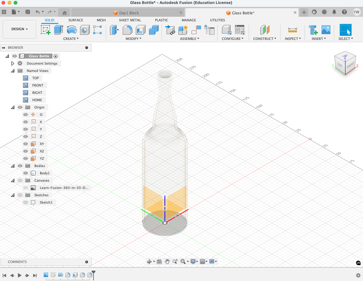
Designed my first water bottle and learned Revolve, Fit Point Spline, Shell, and Appearance. Since the bottle is symmetrical around a central axis, Revolve was the ideal approach.
Sketch vs. Construction Geometry
An important distinction I learned early on: sketch geometry defines the actual profiles used for 3D features, while construction geometry serves as reference lines for alignment, symmetry, and dimensioning. Construction lines appear dashed and cannot be extruded — they only guide real geometry.
| Aspect | Sketch Geometry | Construction Geometry |
|---|---|---|
| Purpose | Creates real profiles for 3D features (extrude, revolve, sweep, etc.) | Reference/guide geometry for positioning and constraining |
| Appearance | Solid lines (blue when unconstrained, black when fully constrained) | Dashed lines |
| Creates 3D bodies? | Yes — directly defines 3D shapes | No — cannot be used as a profile |
| Typical use | Drawing part outlines and feature shapes | Centerlines, symmetry references, alignment guides |
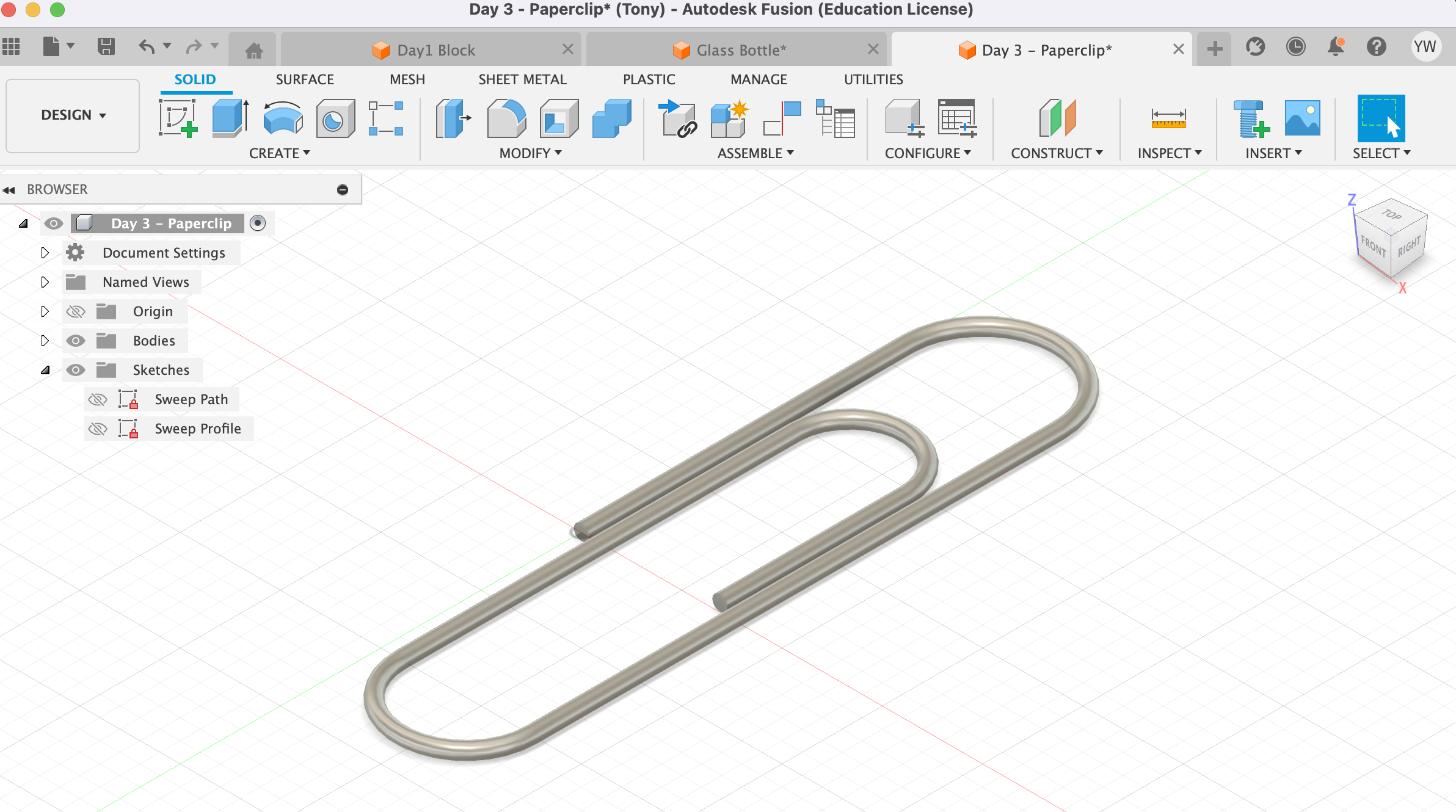
Paperclip
This exercise introduced Sweep, which extrudes a profile along a path. I also learned the difference between Bodies and Components: a Body cannot move independently or have joints, while a Component behaves as a discrete part within an assembly. A fully constrained sketch line turns black instead of blue.
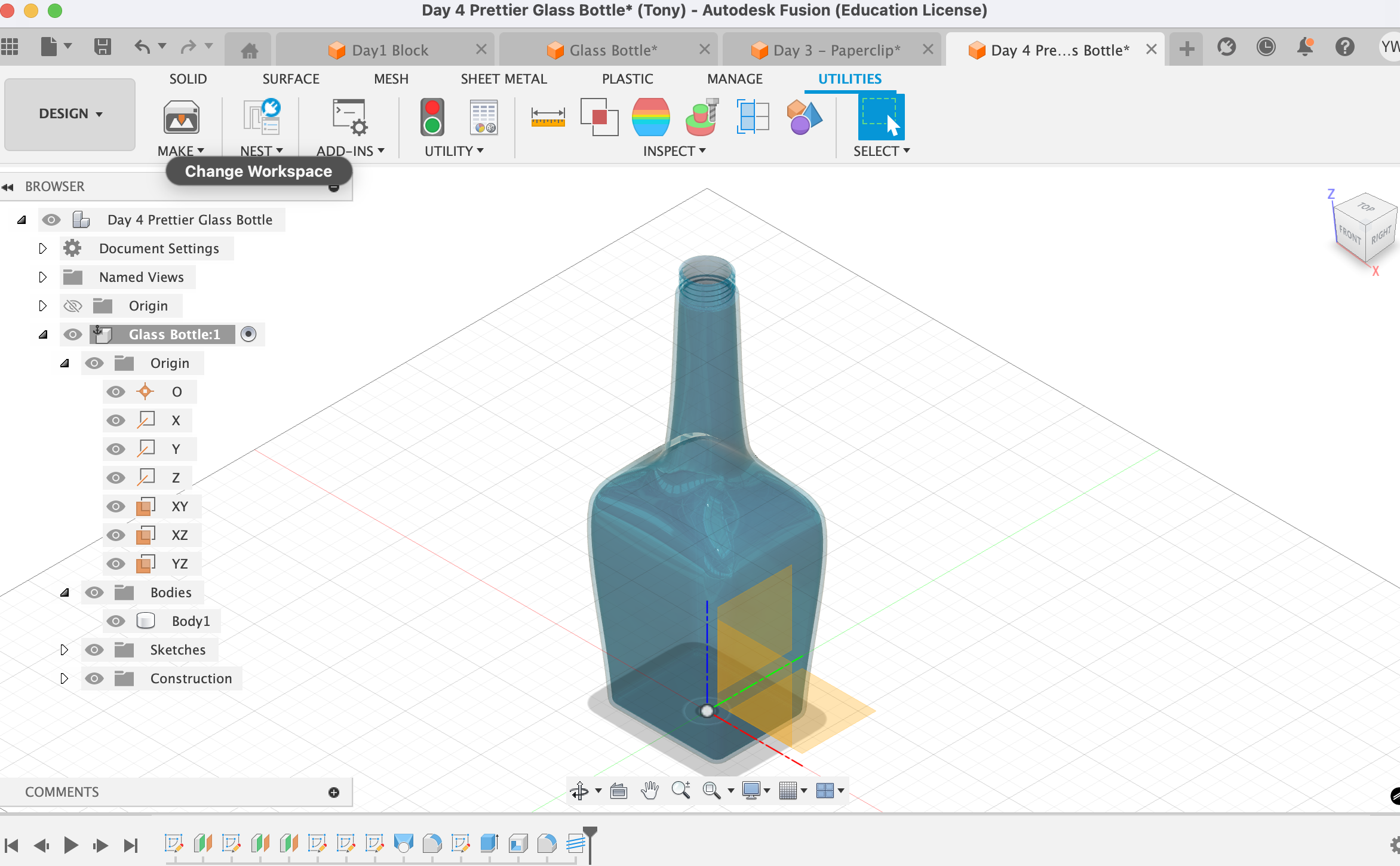
Pretty Bottle (Loft)
Unlike the earlier symmetrical bottle that used Revolve, this one has four distinct sketch profiles on offset planes. Loft connects those profiles into a smooth body, and guide rails control the transition between shapes. I also practiced creating offset planes for positioning sketches in 3D space.
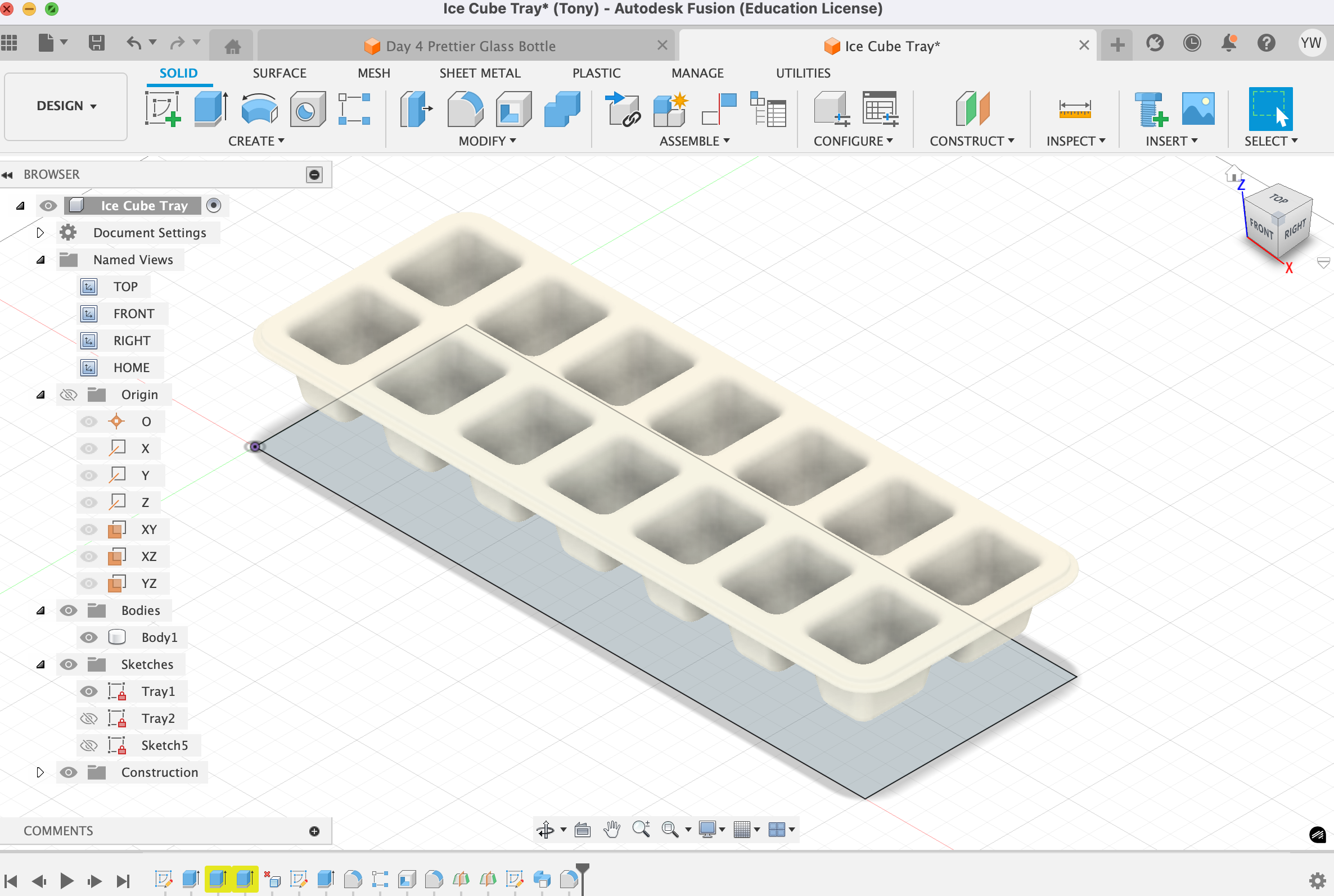
Ice Cube Tray
Practiced Extrude Cut with a taper angle, Shell applied to multiple faces at once, and working with the midplane. The taper makes each compartment slightly wider at the top, just like a real ice tray.
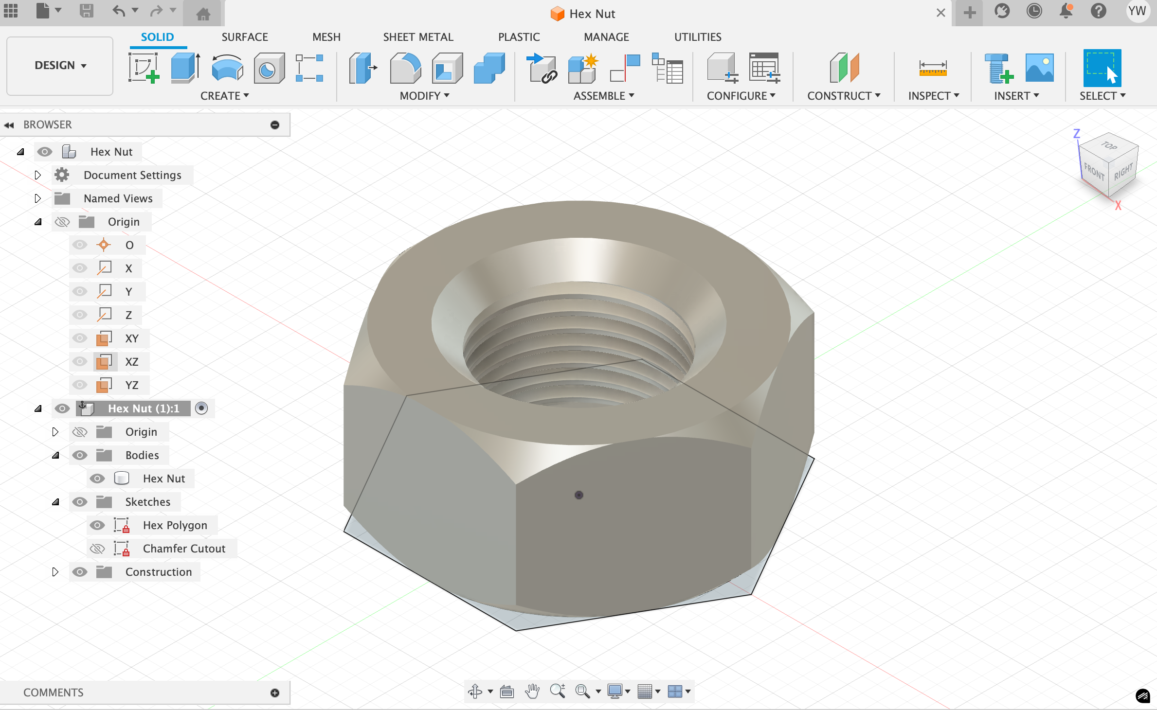
Hex Nut
Learned Circumscribed Polygon for the hexagonal profile, Custom Chamfer for the beveled edges, and the Hole command for the threaded center bore.
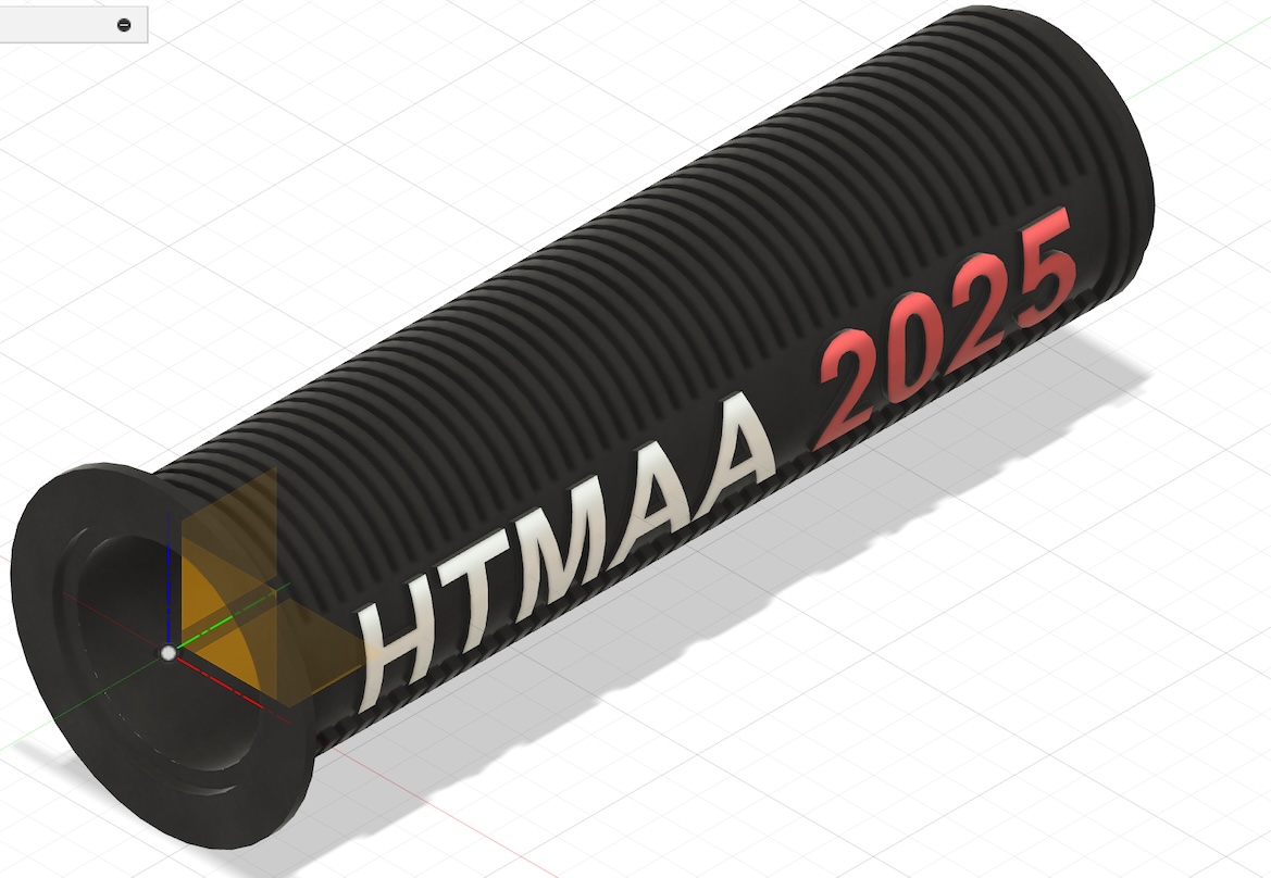
Oct 3rd — Bicycle Grip
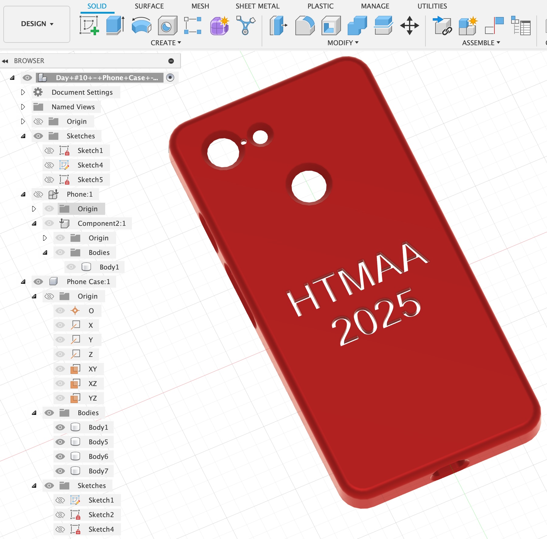
Back with more small components. Learned Emboss Text and Project (tracing 3D geometry down onto a 2D sketch).
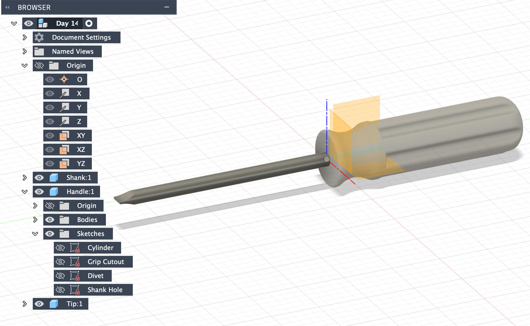
Oct 4th — More Components
Chamfer, Offset
Cylinder, Thread
Extrude Cut — letter A can be tricky
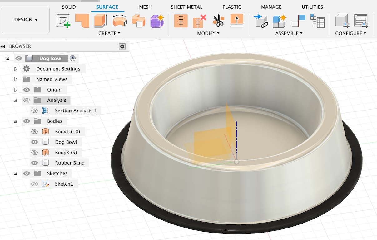
Surface & Thicken
Dec 1st — Assembly Practice
Components & Assembly
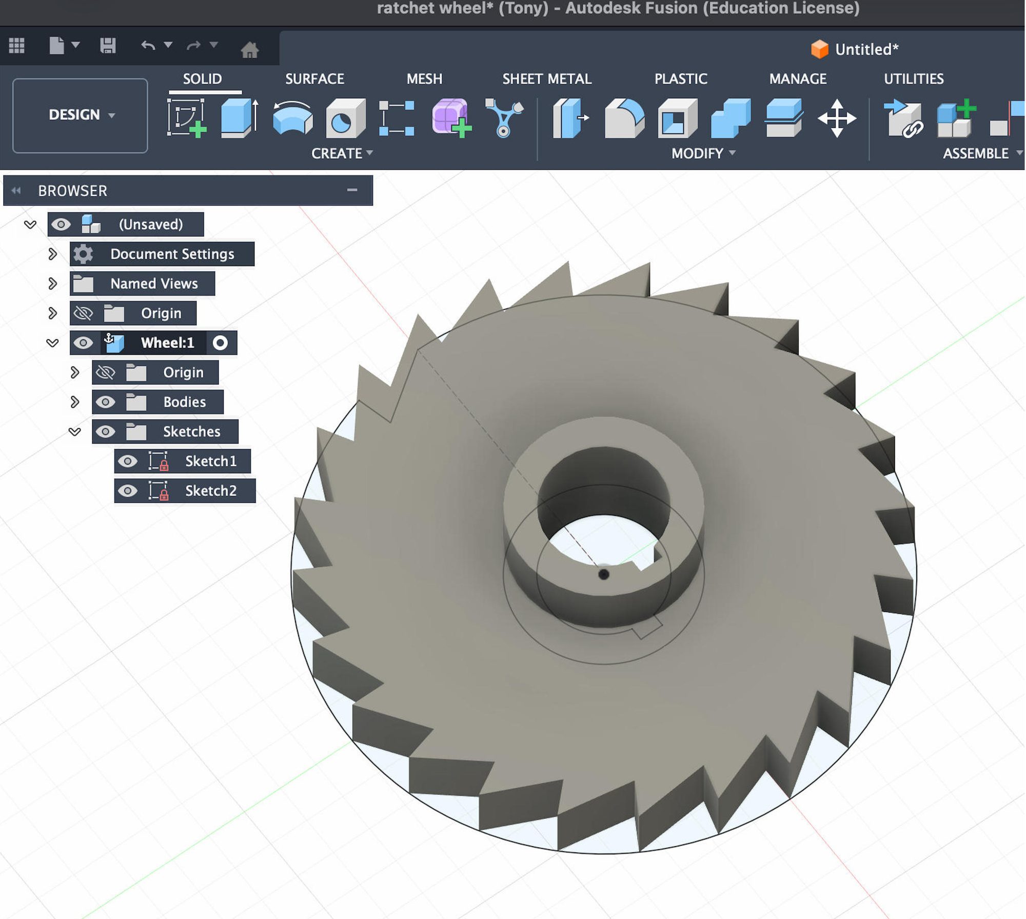
Circular Pattern